Introduction
- Functionality has been added to provide simplified ground support functionality to StopeX,
- Currently in beta stage, and not available in the GUI, however simple edits to the input file give full functionality.
- A database of standard tendon systems are available, custom support inputs can also be used.
User Inputs

User Inputs - Support Method
support method, defines how the supported area will be set in the model. Two options are available:
- ‘step’
The existing step geometry files (defined for the project sequence) will be used to apply ground support. This method will apply to all steps in the model.

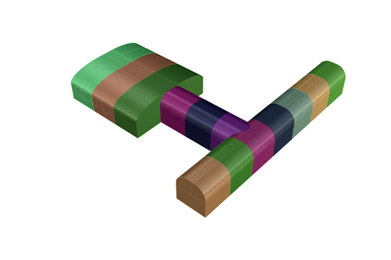
This example shows some tunnels, and a large chamber. each step is coloured. Using the ground support ‘step’ method support will be applied for all excavations
- ‘import-face’
geometry of the supported area must be imported. For example, an stl file for the decline geometry could be imported if only the decline require support.

Using the import-face function, the geometry shown in blue could be imported to selectively apply support to the chamber and selected tunnels
User Inputs - Support Model
Support Model defines the way ground support behaviour is modelled. two options are available.
1. ‘elastic’
Support is modelled elastically; model will still flag when the yield limit of support is exceeded.
2. ‘inelastic’
support is modelled inelastically, capturing the plastic deformation flagging both yield limits and deformation limits
User Inputs - support delay
The support delay options, specify when the ground support should be added to the model. Three options are available
1. Development Support (immediate after excavation)
support is added immediately at the point of extraction. most appropriate where large lengths of development are extracted in one model stage
2. Lagged Support (number of steps delayed)
support is added, a fixed number of steps after extraction. Most appropriate where small segments of development are excavated in each step.
Number of steps to delay by is set by the ‘support_Lagged_step_GS’ variable
3 - Specific model step
User defines a specific step in the model where ground support is added. The ‘support_step_GS’ variable defines the step for applying support

User Inputs - support file name
If the support method has been set to ‘import-face’ then the geometry file name should be specified in the support_filename_GS variable.

If the above excavation is planned, with ground support only installed in the chamber and chamber access tunnel, the geometry on the right should be imported as the import face, file name
User Inputs - support tolerance & Location
The support tolerance variable is used to separate the walls and backs of support geometries to allow support to be applied selectively using the Support_location_GS variable. It’s defined in terms of dip, adjusting the value will primarily affect how drive shoulders are handled (e.g. are they defined as walls or backs)
Typically, the default value for the support_tolerence_GS variable is appropriate; however care must be taken when support is applied using survey wireframes as local surface variation can be misidentified by the routine.

User Inputs - Distance from Floor
The ‘Distance_from_Floor’ variable allows ground support in the walls to be applied above a fixed height (in metres) from the floor. The area below this height does not have support applied.

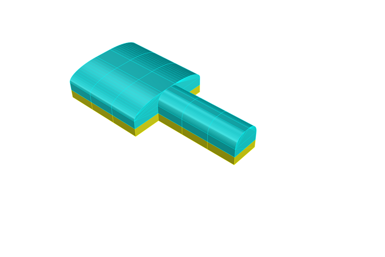
In this example, the distance from floor has been set to apply ground support above the 1.5m grade line. (supported ground in blue, unsupported in yellow)
User Inputs - Support Type
The support type option allows selection between tendon style support or shotcrete/liner style support. A third option allows both tendon and shotcrete combined support systems.
Each support type is applied as a liner in FLAC3D, StopeX calculates the implicit support provided by the bolting pattern, length and strength properties to model the resistive forces as a liner element in FLAC.
User Inputs - Support Name
A user defined name may be applied to the support group. In addition approximately 50 default support types are included in StopeX, in the beta version setting the support name to match any of the systems shown at the end of this presentation will automatically populate the strength parameters based on verified ground support strength testing for each system.
User Inputs - Support Properties

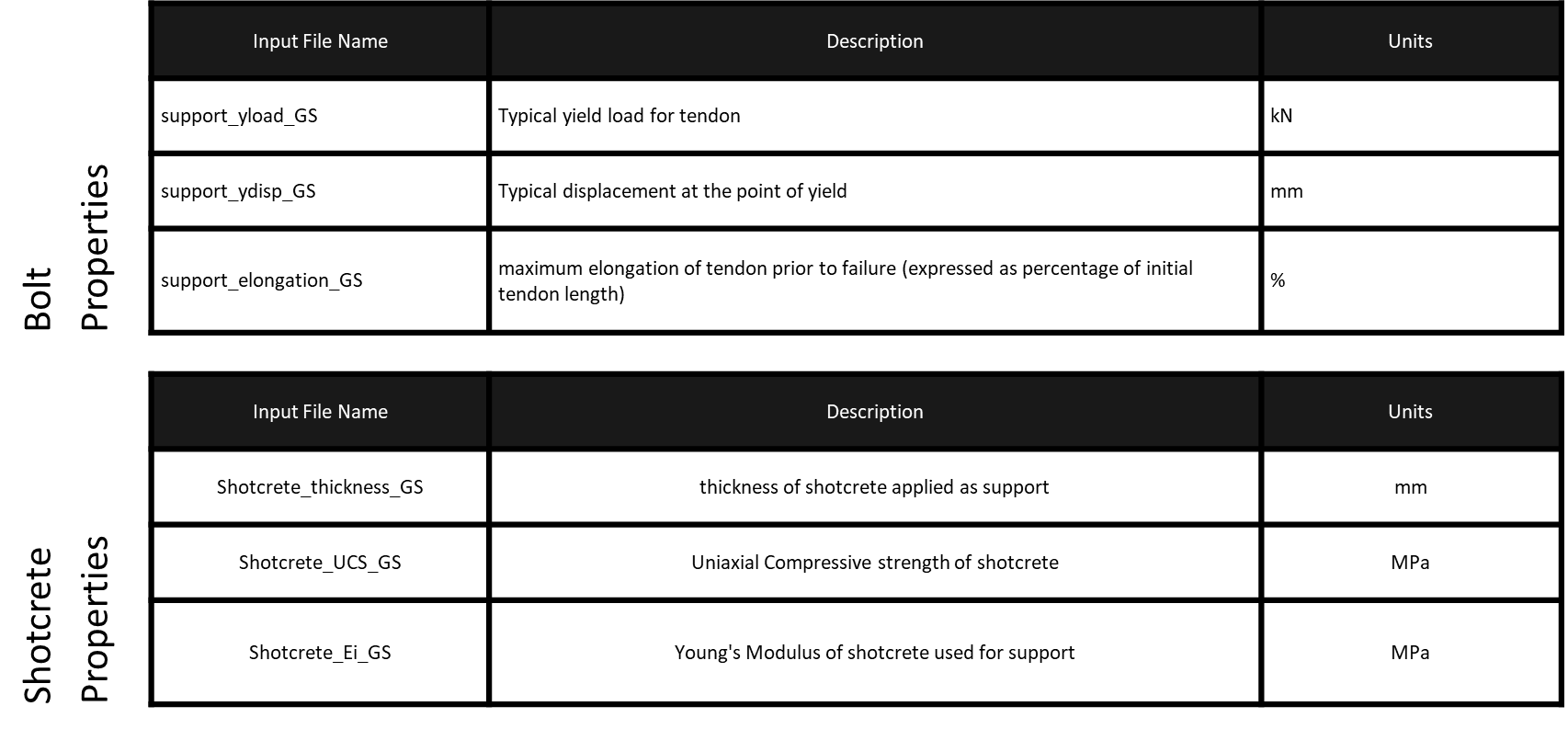
User Inputs - Bolt Property explanation

User Inputs - Bolt layout
The final variables are to define the layout of bolting, and length of bolts to be used.
support_bolt_spacing_GS is used to define the spacing of bolts perpendicular to drive direction
support_ring_spacing_GS variable defines the distance along a drive between support rings
support_element_length defines the installed length of bolt to be modelled.