If you have never built a model before, these definitions might help!
The terms Mesh, Meshing, and zones are used widely across the forum guidance material and throughout the modelling process. If you aren’t sure what the terms mean, here is a brief explanation:
‘Zones’ – Zones are the individual blocks of information that a model uses to run its calculations, for most people in the mining world, it may be easier to think of them as a type of block model, each zone will have information in it relating to geotechnical parameters, domains, or the extraction sequence and when viewing the results outputs such as displacement, velocity, strain, and induced stresses can be viewed for each of the zones.
‘Mesh’ – Refers to the full model, including all the zones
‘Meshing’ – The process of building the Mesh, StopeX does most of the work for you with a few inputs, however you have control on how small or large the zones are, and the total number of zones that you are happy to process. (The more zones there are, the longer processing will take.)
Global Octree Meshing Parameters
StopeX carries out an automated mesh building process, creating a model mesh appropriate for the model that is being run. User controls provide targets and constraints for the automatic meshing process and allow the user to tune the size of the model that will be solved in FLAC3D.
The target number of zones in the model, is the total number of zones targeted by StopeX in the mesh construction.
The value set in the ‘far field’ zone size will dictate the available zone sizes later in the model construction. The far field zone size can be very large as they are used to fill the model away from any excavation.
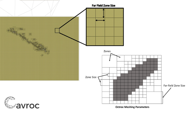
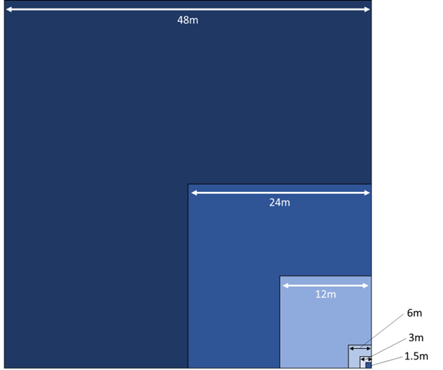
Smaller zones will be used for the model geometries, the smaller sizes that are available are determined by splitting the largest zone size in half repeatedly, as shown in the example below, so the size chosen here will affect the options available later in the set up process. The image below demonstrates the zone sizes that will be used in a model if the far field is set to 48m.
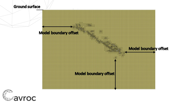
The Model Boundary Offset option controls how far the external boundaries of the model are extended form the excavation geometries. The boundary should be sufficiently far from the model to avoid ‘edge effects’. A good starting point is to look at the maximum depth of the mine and use the same value as an offset.
Zone Size during initial Iteration sets the minimum zone size that is used during the first iteration of model construction, and should be appropriate to represent geometries that require the highest accuracy. The automatic meshing process will increase the size of zones (or decrease them depending on the target total zones.)
Model Construction Tab
The Geometry files
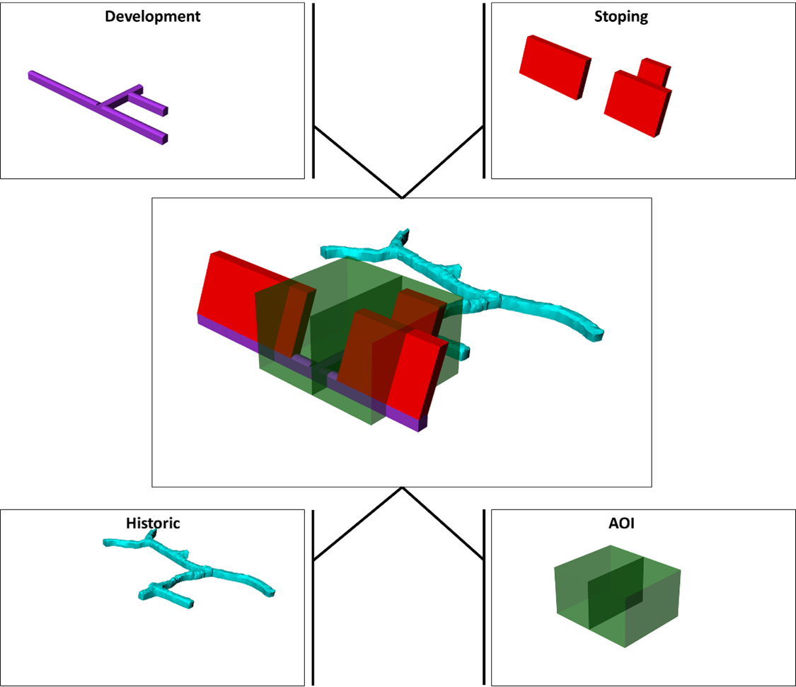
Within the Model construction tab, there are categories relating to the different elements that can have unique meshing parameters applied. Each requires a geometry file to be imported representing each of the categories. The image below shows an example model, and the individual geometries that would be imported to each tab.
For reference the example model includes six stopes, some a small amount of planned development, and a section of development that has been previously constructed. The AOI is included for this model for analysis of the pillars left between stopes.
Mesh Settings
Each of the tabs have a range of mesh settings available, that allow specification of the desired mesh accuracy with a small number of inputs.
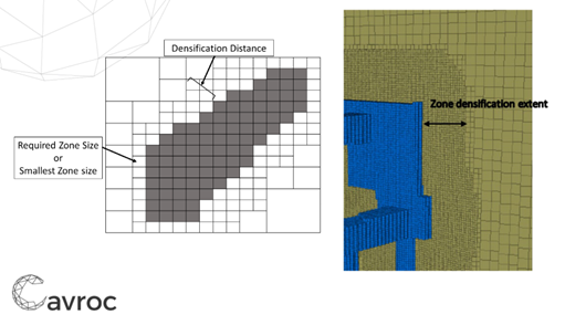
Zone Densification Distance
The zone densification distance allows the mesh properties to be extended away from the imported geometries, allowing the high resolution to include areas of damage or stress redistribution around the outside of excavations.
Relative Geometry Accuracy
The relative Geometry Accuracy defines the size of zones that are applied on the imported geometry boundary the options available work by multiplying the ‘zone size Multiplier during Initial Iteration’ as below
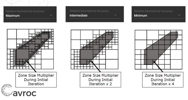
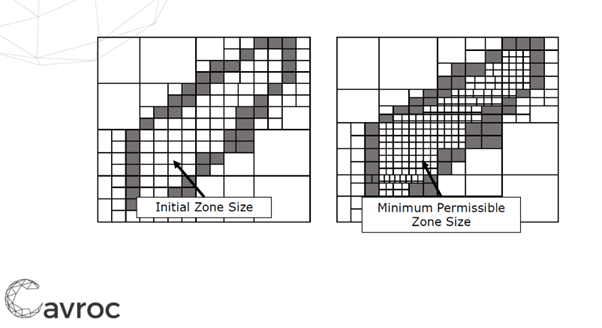
Initial Zone Size
The Initial Zone size is applied during the first meshing iteration, and is used to define the geometry accuracy, however if the total number of zones is below the target number, their size may decreased. The minimum permissible zone size puts a hard limit on how small zones can get within the specific geometry.
