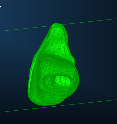
Computers may mesh an object incorrectly when working from scanned data. This is not likely due to any errors in scanning, rather the computer has made an error regarding the points we consider part of the geometry. The geometry we have been using (see below) as an example looks fine on the surface, however when you take a cut plane there is more to the geometry then you can initially observe. When you look at a cut plane you can observe that the example geometry has internal voids, pockets, holes and normal’s facing in the wrong direction. This will often result in errors when processing later. Therefore, these defects need to be fixed. One way to solve this problem would be to wrap geometry around the outside layer and delete anything internal. The wrap geometry command in CAD Processor can be used here
FIGURE 6 - CAD PROCESSOR - ERRANT GEOMETRY
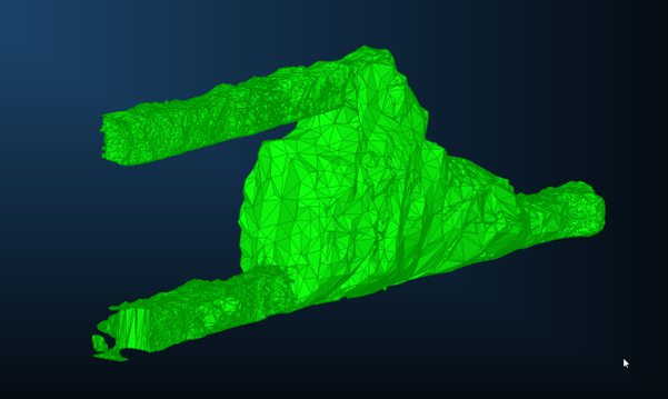
FIGURE 7 – CAD PROCESSOR - INTERNAL INCONSISTENCIES OF GEOMETRY
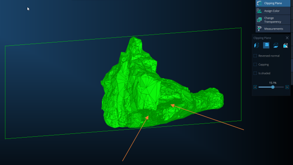
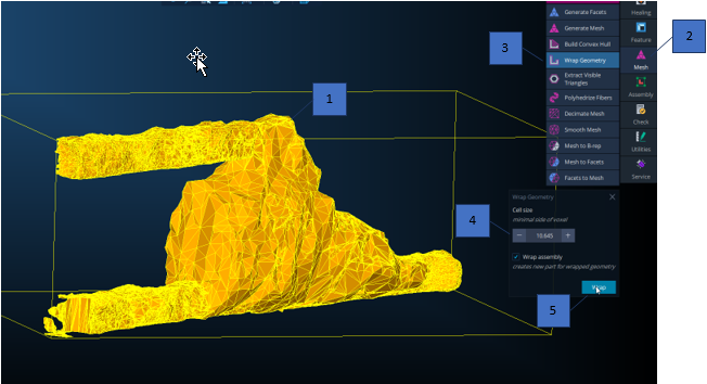
To do this, the steps are as follows:
- Select the object to be wrapped. When you do this the object will turn gold in colour.
- Select the Mesh dialog
- Select Wrap Geometry
- Enter a cell size, in this case a cell size of 2.0 was sufficient
- Click ‘Wrap’
FIGURE 8 - CAD PROCESSOR - WRAP GEOMETRY
The resultant geometry is as follows:
FIGURE 9 - CAD PROCESSOR - WRAP RESULT
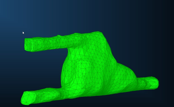
Note that the geometry is much smoother. But also, a lot of the erroneous meshing has been removed. Taking a cut plane reveals a void.
FIGURE 10 - CAD PROCESSOR - INTERNAL ERRORS FIXED
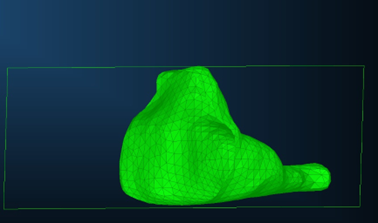
FIGURE 11 - CAD PROCESSOR - INTERNAL ERRORS FIXED
