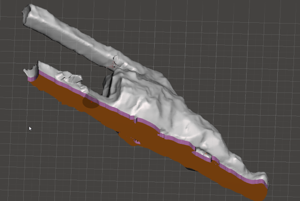
In this example, a flat base will be added to an existing geometric object. Meshmixer will be used for the example to add the flat base to the model. The software is free to use and good for editing complex meshes, like those resulting from scans. Meshes can be edited, shaped, sculpted and repaired using this program.
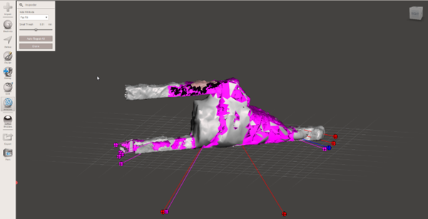
To begin, open Meshmixer and import your geometry. As you will see below, our sample geometry has quite a few things wrong with It (highlighted in red). To begin, select analysis, followed by inspector. Figure 16 shows the result of the auto repair routine. You may be tempted at this point to hit ‘Auto-repair All’ and in some cases this is fine. However, the magenta highlighted areas will be deleted and so will most of the model. You can see this by pushing F1 with the Inspector tool selected, which will bring up the help dialogue.
FIGURE 16 - MESHMIXER - INITIAL IMPORT
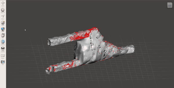
FIGURE 17 - MESH MIXER AUTO-REPAIR
Deleting half the mesh here is less than ideal, so a different approach will be required. One of the errors we’re getting for this particular file is a ‘flipped normal’. For those who don’t know, a flipped normal is when an STLs normal points in the ‘wrong’ direction when compared to the rest of the model. Figure 18 shows some critical steps when dealing with this problem.
In this part we use the select tool to bring up the select dialogue. From here we can choose to use a spherical brush and we adjust the brush to the size that’s appropriate for the geometry being worked on. The Filters dialogue is important to understand. If you find you cannot select the ‘flipped normal’ (shown in shaded pink) you need to tick the box that says “allow back faces”. The Crease Angle Threshold is important too. It tells the program what to select based on the angle to the ajoinging parts of the mesh. A value closer to 90 will not select anything, unless is 90° opposed to the mesh next to it. In our case, because the normals are flipped, this will be true in most cases. As left clicking and drag allows you to paint over the areas you wish to select. They will turn black as you select them. If you see flecks of orange appearing this means you’ve selected the grey face with the correct normal and will need to deselect these areas highlighted in orange. Pushing ctrl+select, will deselect these areas. When you have filled in all the pink area, you can select edit at the top of the selection dialogue and then “flip normal” from the dialogue (see Figure 19). Your normal will now be in the correct orientation.
FIGURE 18 - FLIPPED NORMALS
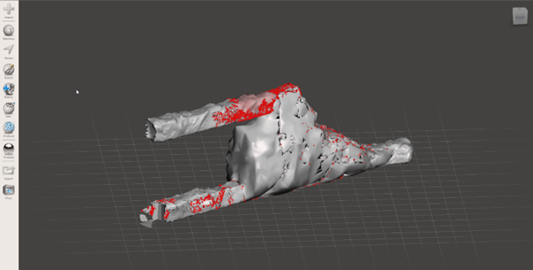
FIGURE 19 - FLIPPING NORMALS
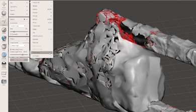
FIGURE 20 - SELECTING OBJECTS IN MESHMIXER
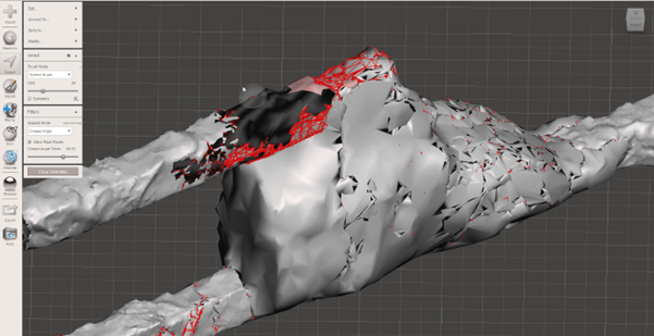
You may be tempted to try ‘remesh’ from the edit dialogue at this point, and it may work for more simple geometry. However in this case, there’s a much faster and easier way to repair this STL. From the Edit menu select “Make Solid”. Meshmixer will try it’s best to delete any troublesome internal geometry and turn the object into a solid. If we try this option before fixing the normal, ‘make solid’ may attempt to remove it from the file. Ideally we don’t want this, so that’s why we took the time to flip the normal back to…normal.
FIGURE 21 - MAKE SOLID
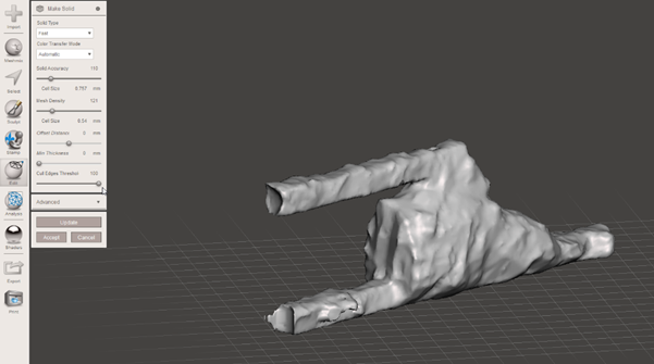
Running the inspector again, Figure 20 shows a definite improvement. Hitting the auto repair here, will delete those smaller elements highlighted in magenta.
FIGURE 22 - INSPECTOR AFTER MAKE SOLID
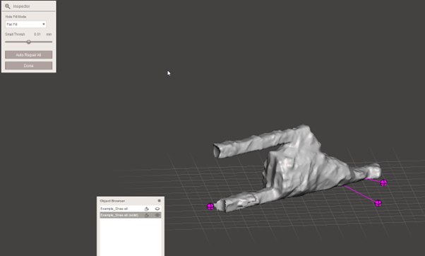
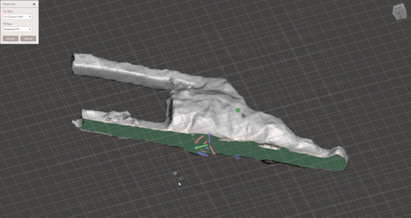
Another way to perform this same function is detailed in section 2.3 on page 6. Wrapping a mesh using CAD Processor will accomplish the basically the same thing, with less work. To add the flat base to the model, Select edit and then choose “Plane Cut”. Note the little S in the circle surrounding the gumball. If it is solid green, it means mesh mixer is in “snap mode”. This can be annoying if you want to be exact with your commands, so I suggest turning it off by clicking on the green S. By adjusting the height, position and angle of the cut plane, you can slice the bottom off the model.
FIGURE 23 - CUT PLANE
Using the select tool, select part of the base. Then, still in the select menu, go to modify and have a look at the new options. The one that we will use is “Expand to groups”. Push it and you will see the entire coloured area is now selected. So what happened? Meshmixer treats this whole area as one group. By selecting part of the group and then expanding the selection we captured the entire base.
Still in the same menu, go to Edit, then click “extrude”. This will bring up a new dialogue. Set the offset to 2mm. You will see that the model now has a nice flat base. This model can now be used for applications like 3D printing, where a flat base is required.
FIGURE 24 - SELECT GROUP
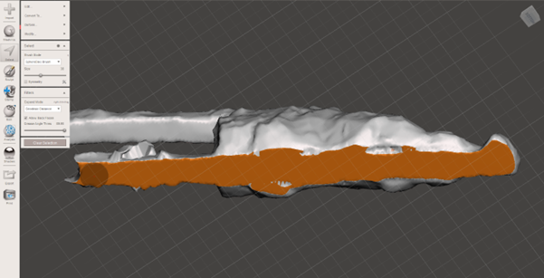
FIGURE 25 - EXTRUDE BASE
