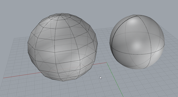
In Rhino, there are a few key concepts to understand about how the software ‘draws’ each object. Figure 25 - Mesh vs Surface, below shows two shapes. The sphere on the left is a mesh object, whereas the sphere on the right is a surface object. The meshed sphere is blocky in appearance and is made of a series of simple polygons, whereas the sphere on the right is smooth.
FIGURE 26 - MESH VS SURFACE
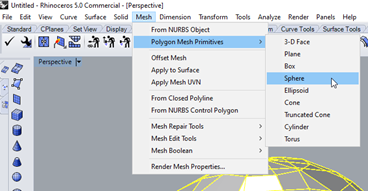
You can generate the mesh sphere by clicking on mesh -> polygon mesh primitives -> sphere (see Figure 26), or by using the command _meshsphere
To generate the surface sphere, you select Solid -> Sphere -> Centre Radius
FIGURE 27 - MAKE MESH SPHERE
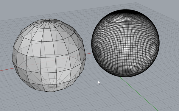
The polysurface can be turned into a mesh, by using the command _mesh. Select the surface and then use the mesh command and you will see a dialogue. More polygons will make the mesh more accurate, however this will be at the expense of processing time and file size. The program needs to draw each individual polygon to approximate the circle. In contrast a surface is a set of instructions the computer gives the program how to draw the sphere. It is a subtle distinction, but one important to understand. For those familiar with image formats, a surface is more like a vector graphic format (a script that tells the computer how to draw the image), whereas a mesh is more like a jpeg (a file that contains information as to what colour each pixel should be). Figure 28 below shows a coarse mesh on the left and a fine mesh on the right.
FIGURE 28 - MESH DIFFERENCES
The next question you may have is, can we reverse that process. The answer is yes! Select the mesh and use the command _MeshToNurb. The program will now attempt to generate a poly surface that approximates the mesh. So what is a NURB? A NURB is a Non-uniform rational basis spline, or in English it’s a line that tries to approximate a curve by drawing a line between the points on a mesh. Points are where the mesh polygons intersect. In this example, Rhino can do this quite easily, but this is a very simple mesh and approximating complex geometry using NURBS can be very processor intensive. Conversion may take a long time and can crash the program easily as the computer tries to draw lines that will approximate the shape.
A mesh panel can be thought of like making a structure using flat panels of glass. From a distance the conic section will appear like a smooth cone, despite being made entirely of flat panels. In contrast a NURB is like a panel of moulded plastic that is curved.
FIGURE 29 - GLASS CONIC
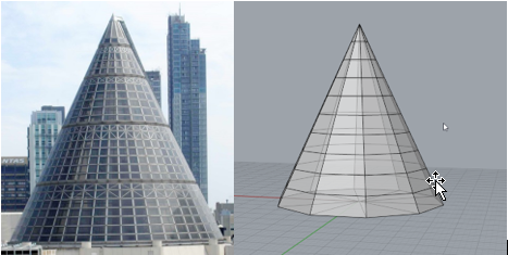
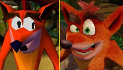
So, which one do you want to use? Computers have an easier time performing calculations related to meshes. Graphics Cards are an example of dedicated hardware designed to essentially draw triangles. However, a mesh always has limits as it does not scale efficiently. Zoomed all the way in, a mesh is just flat triangles that approximate a shape. It’s no really drawing the actual shape. For our purposes an approximation is all that is necessary, so the answer is accepted. But there is no mesh capable of completely approximating a curve because you must make a point somewhere along the edge of the shape to define the panel. Every point of data uses part of the computer’s memory. The more detailed a render needs to be, the more data is going to be required. This can be best illustrated by comparing graphics from the mid 90’s to graphics 20 years later. Pay particularly close attention to any curves that had to be approximated, for example the eyes in the image below. Much better images could be drawn by comparison as processors got faster and computers had access to more memory.
FIGURE 30 - GRAPHICAL COMPARISON
Another important question is to ask, how can you work with multiple meshes? For example, say we want to add a “walkway” to a conic section. First, we draw Two mesh objects using meshcone and meshcylinder. The result will be what is shown in Figure 31. The shapes are in the wrong orientation, but clicking the cylinder will bring up the “gumball” (Figure 32). To rotate the object in a given orientation, you can click the click and drag the curved, green, blue and red arc lines. Using the arrows, you can reposition the shape. Dragging the boxes at the ends of the dashed lines will scale the object. If you hold shift while scaling the shape will scale evenly.
FIGURE 31 - ADDING SHAPES
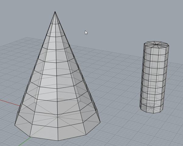
FIGURE 32 – GUMBALL
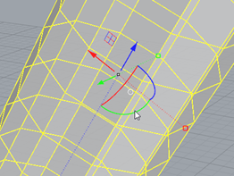
FIGURE 33 - WALKWAY INTERSECTING CONE
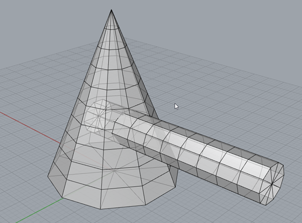
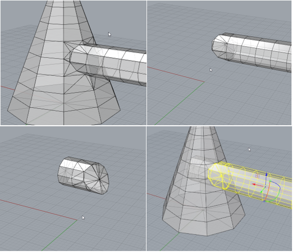
Eventually, with a bit of practice, you can arrange the shapes such that they resemble Figure 32. But these are two meshes that just happen to be intersecting. You may wish to combine them into a single shape. For this purpose we will use the command, in the ‘mesh tools’ tab. There are 4 important commands here. Those are Union, difference, intersection and split. The images give you a clue as to what each one does. In Figure 34 we see the output of these functions. A union joins the meshes together, a split separates them into two separate parts. An intersect returns the geometry that intersects with the other and a difference chops off whatever was selected second. This is key to remember, the order which you select the objects will effect the output, but that’s why we have ctrl+z.
FIGURE 34 - MESH TOOLS
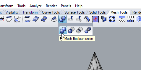
FIGURE 35 - UNION, DIFFERENCE, SPLIT, INTERSECTION
What if you want to delete some of the “glass panels” from the walk way. One way to do that would be to use the command DeleteMeshFaces. Type the command and then select the panels you wish to remove. They will turn black. Push ctrl+clicking will reverse this decision and keep the panel.
FIGURE 36 - DELETING MESH FACES
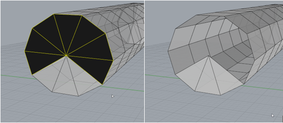
To reverse this, we can try the command, _fillmeshhole. Try typing the command then click the edge where the panels were just deleted. You will observe that the panel is put back onto the shape. This can be really handy if you have a mesh that has a hole in it. Certain mesh geometry needs to be ‘manifold’ for tasks like calculation and 3D printing. Sometimes you may see an error with non-manifold geometry. To explain very simply, manifold geometry can exist in the real world and if you poured water into it, it would hold the water. Non manifold geometry cannot exist in the real world. It is very possible for a computer to draw geometry that cannot possibly exist.
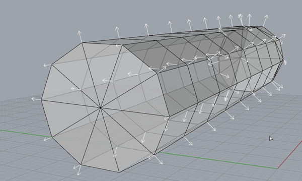
Another thing to watch out for are mesh normals. Any 3 points in space can be used to define a plane. But, which direction is it facing? For 1 plane, the decision is arbitrary, but we have complex geometry made of many planes. The computer needs to know that all the planes are oriented in a direction that makes sense. Try the dir command click your mesh. The arrows in Figure 35 show that all normals are pointed in directions that make sense for this object. If for whatever reason this is not the case, the command unifymeshnormals, can try at auto repairing the issue. When in doubt, launch _MeshRepair to start the automatic repair process that also fixes other issues like non-manifold geometry and parts with no thickness. It is entirely possible for a computer to define a plane with a thickness of 0. However, in the real world, that cannot exist. So, the computer will either need to thicken that plane, or delete it entirely, otherwise it can cause issues for other programs, i.e. dividing by zero.
FIGURE 37 - MESHNORMALS
