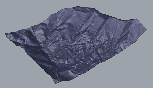
This is a technique to extend the boundary of a topographical map. You may wish to do this if the topology provided just covers the area where the mine is. The boundary of the map needs to be sufficient distance away from the model so that the boundary condition at the edge of the model does not affect the result. What the topology is at the surface is largely irrelevant and can be considered flat ground for our purposes, but this flat ground still will be needed to be added into the file. Take the following topology for example.
FIGURE 38 - TOPOLOGY EXAMPLE

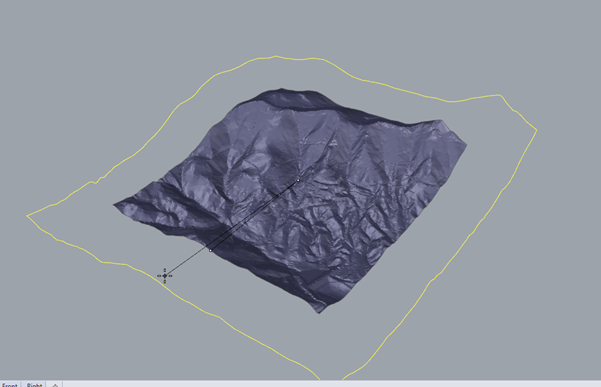
We begin by using the following command, DupBorder. This command creates a curve or polyline around the edge of the mesh. Type the command in the command bar, select the topology and push enter. A yellow border will now be displayed around the edge of the topology. This command can also be found in Curve -> Curve from Objects -> Duplicate Border.
We want to define our new border from this curve we have just created, but we need a reference to start the scaling from. A good way to do this is define a point related to the centre of the object. The command _AreaCentroid, accomplishes this. This command can also be found in, Analyze -> Mass Properties -> Area centroid. A white dot will appear in the centre of the mesh which we can use to start scaling the topology.
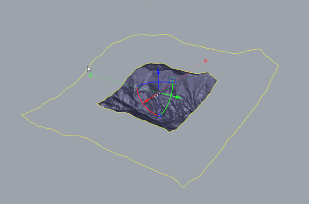
Use the Scale command to increase the size of the curve we just created. This part is important. Do not select the mesh. Selecting the mesh will scale the entire model. This is a good thing to know, but not what we’re trying to achieve. Select only the curve we just created with the border command. Select the reference point in the centre of the topology, then select an edge of the model and use the mouse to scale. Press enter when done. You should end up with something that looks like Figure 38, below. At this point we need to fill in the gap between our new border and the existing topology. But before we use meshpatch to make a mesh between two curves, we need another border that surrounds the topology. Luckily, we know how to do that because that was the first thing we did. Select the mesh and use the _DupBorder command. To select multiple objects, hold the shift key and click on both borders. You will end up with something that looks like Figure 39.
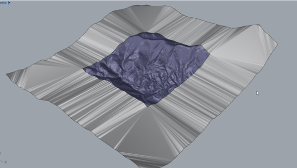
Select both borders and use the command MeshPatch. Nothing will happen yet because the command needs one last piece of critical information. It needs to know where the hole is. The hole in the model is the existing topology. Not defining this hole will cause the patch to cover the entire surface, inclusive of the topology. This will affect any result done later by another program (such as FLAC3D) because as far as the computer is concerned, the new patch will be the topology. What we want to do is have our original mesh preserved within the new one. Check Figure 40 for the result. There are few things left to check. Sometimes the meshing is not perfect, and parts may be left out. Use the edge analysis tool to check by typing the command, ShowEdges. Select the new surface and you will see pink lines bordering the shape. You can select “naked edges” Then click on “Zoom” to show the model edges. Ideally you will have a pink line bordering the topology. However, there may be some edges left over that have not been patched.
In Mesh -> Mesh Repair tools you will find the command MatchMeshEdge where you can select these broken edges and tie them into the main model. You can also do things like “filling holes” in the mesh that was discussed in section 2.3.
FIGURE 39 - SCALED BORDER

FIGURE 40 - BOTH BORDERS

FIGURE 41 - FINISHED PATCH
